![]() Click Here To Download A Printable PDF User Guide
Click Here To Download A Printable PDF User Guide
Getting data from serial port to USB drive
QUICK START
- If transmit unit is not set to 9600 baud, set config.txt file on USB stick to match data transmission.
- Plug dogcatcher into transmit unit. See Pinout section for details.
- Power the Dogcatcher 2 with the power supply included in the kit or with dc voltage between 8 and 30 volts.
- Ensure green LED is blinking or on, which means power is good. If the LED is not blinking and you used your own power supply, ensure that you did not reverse power and ground.
- Plug in memory stick. The green LED will go from blinking to solid on.
- Allow data to be logged.
- If necessary, push button on Dogcatcher 2 next to USB stick to close file on USB stick and allow safe removal of USB stick. Do not remove the stick when the amber LED is solid on.
- The data may be read from the stick by any computer with a USB port.
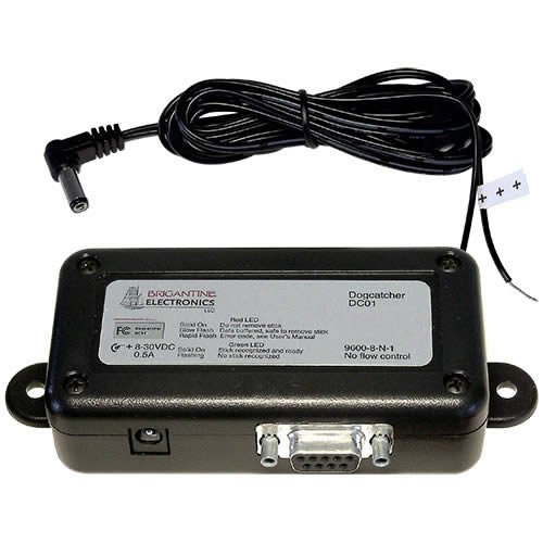
INTRODUCTION
The Dogcatcher 2 is a serial data logger. It is designed to be easy to use without configuration yet flexible for a wide range of tasks. RS-232 baud rate, timestamping and capture filename can be set through a configuration file on the USB stick, and can be saved in flash onboard the Dogcatcher 2. Data is stored on a standard USB memory stick. The Dogcatcher 2 is designed for use where a computer would be insecure, too expensive, too large or impractical.
SPECIFICATIONS
- Input voltage: 8VDC-30VDC
- Input current: Internally fused at 0.75A. Actual current draw depends on memory stick used. Typical current draw is 0.1A.
- Timestamping can be configured to occur after a user defined character of character pair.
- Communication settings: The baud rate is 9600 bps by default, or a value set in config.txt. Permissible values range from 2400 baud to 230,400 baud. The Dogcatcher 2 is set to 8 bits per character, no parity, 1 stop bit, no flow control. RS232 standard voltages.
- Handshaking may be configured as RTS/CTS or NONE.
- Unless changed in the configuration file, writes data after 64 bytes received, or 7 second timeout between received bytes.
- Flash drive must be formatted for the FAT32 file system. The majority of flash drives satisfy this requirement.
OUTPUT
Except for user enabled timestamping, the Dogcatcher 2 writes data to the USB stick exactly as it is received over the serial port. Tab delimited data remains tab delimited. Comma separated data remains comma separated. Images and other binary files will be uncorrupted. The filename of the data logged is either CAPTURE.TXT by default, or a name set by the user in config.txt. The user may rename the output file to have an extension appropriate to their data type.
Configuration Options
Configuration options are set in config.txt on the USB stick. They are parroted back in the actualConfig.txt file written by the Dogcatcher 2 to the USB stick. A user wishing to change options may place a USB stick in the Dogcatcher 2 to have the actualConfig.txt written to the USB stick. The user may then modify the file name to config.txt and modify the settings as needed, for example changing baud=9600 to baud=115200
The options available are listed in the table below.
| Name | Factory Default Value | Description |
|---|---|---|
| baud | 9600 | The baud rate at which the Dogcatcher is to receive data. Supported rates are 2400, 4800, 9600, 19200, 38400, 57600, 115200 and 230400. Other rates between 110 and 921000 may work, but are unsupported. |
| flowControl | NONE | Supported options are NONE and RTSCTS. |
| capturefile | capture.txt | The name of the file on the USB stick where data will be logged. If this file does not exist, the Dogcatcher 2 will create it. The capture file name should be 1 to 20 characters. |
| doNotAppend | FALSE | If FALSE and a file by the capturefile name exists, new data will be logged to the end of the existing file. If TRUE and a file by the capturefile name exists, new data will be logged to a file which has an incrementing number appended to the base of the capturefile name. For example, suppose capturefile is capture.txt and doNotAppend is true and a the USB stick has capture.txt on it. New data will be written to capture1.txt until the stick is removed. When the stick is reinserted, data will then be written to capture2.txt. |
| timeStamp | FALSE | If true, a timestamp and colChar will be inserted after each lineTerm string received. |
| TSLineTerm | \r \n | String which, when found in the incoming RS-232 data, will be followed by insertion of a time stamp. Maximum 2 characters in the TSLineTerm string. Has no effect if timeStamp=FALSE |
| TSColChar | , | Character which is inserted after any timestamp which the Dogcatcher inserts. May be comma, space or any ascii character. Has no effect if timeStamp=FALSE |
| LEDDim | 5 | Adjusts the brightness of LEDs. Can be used for power savings when using a battery. Allowable values are 0-9. 9 turns off the LEDs entirely. |
| Bufferbytes | 64 | In order to avoid overly fragmenting the memory on a USB stick, the Dogcatcher will not write the received data until (1) bufferbytes (e.g. 64 bytes) have been received or (2) periodicClose has expired without more data arriving or (3) the pushbutton is pushed. |
| periodicClose | 7 | Every periodicClose seconds, all buffered data will be sent to the USB stick, then the capture file will be closed for 3 seconds. Data is written after periodicClose, even if less than bufferbytes has been received |
| uartstatus | FALSE | If true, device status will be sent on TX pin of RS232 port. Otherwise, TX pin of RS-232 port will be in the idle state. |
| RestoreFactory Defaults | FALSE | Sets unit to factory default settings. Does not affect NVRAM. After power on reset, unit will return to user settings. To permanently restore to factory defaults, the user will have to use the file SaveUserDefaults.txt |
| IgnoreRTCLostP WR | FALSE | If set to TRUE, the Dogcatcher 2 will not generate an error if the real time clock loses power. This directive will only work if it is set as a user default in flash |
| RemoteLEDs | FALSE | Only applies to units with terminal block. This allows the user to wire remote LEDs to the three outputs. The remote status lines will work exactly the same as the LEDs on the unit. A low logic is expected to turn the LED on. The user must provide a current limiting resistor on the status output. |
| RemoteStatus | NONE | Only applies to units with terminal block. This sets the status pins on the terminal block to give a status similar to the LEDs. If an LED would be off (green LED off for no stick), the corresponding remote status bit is logic low. If an LED would be blinking or solid on, the remote status bit is logic high. |
To set device defaults – If a blank file of name SaveUserDefaults.txt is on the USB stick, the Dogcatcher 2 will write the current device settings to onboard flash and will erase the SaveUserDefaults.txt file on the USB stick.
To use configuration options.
- Get ActualConfig.txt. Dogcatcher 2 will write this to any stick inserted.
- Modify the settings as needed. Refer to this document for available options. Save this file as Config.txt in the root directory of the USB stick.
- Insert stick with Config.txt into the Dogcatcher 2 and power cycle.
- Take stick to PC and verify settings in ActualConfig.txt are as desired.
- Create file SaveUserDefaults.txt on stick in order to save these settings to flash on the Dogcatcher. Once the settings are in flash (non-volatile RAM) they will be set automatically on power up.
- Insert USB stick in Dogcatcher2.
- Power cycle and verify ActualConfig.txt contains the desired settings.
Dogcatcher2 is ready for deployment.
To configure several Dogcatcher 2 units, get working settings in the Config.txt file. Then add the SaveUserDefaults.txt file and set its attributes to read only, which will prevent the Dogcatcher 2 from deleting it. Now insert the stick into each Dogcatcher 2 you wish to modify. It is very important not to have a read only SaveUserDefaults.txt on the stick used for data logging because writing flash memory repeatedly will shorten the life of the Dogcatcher 2 and will not be covered under warranty.
Timestamping
The real time clock can be set either from the USB stick or by an RS-232 date time string. The clock can be set through a SetTime.txt file on the USB stick. This file is read and the time is set when the USB stick is inserted. Once the Dogcatcher 2 uses SetTime.txt, it deletes the file.
To set the time through the Dogcatcher 2 serial port: (1) Remove power and any USB stick from the Dogcatcher 2. (2) Push and hold push button switch or activate remote switch (3) Power on Dogcatcher 2, you may release button when the prompt is sent to the serial term software (4) Send RS-232 date time string.
Time must be in format MM/DD/YYYY HH:MM:SS\r.
If your application will never make use of the time stamping feature, you may wish to set the configuration line “IgnoreRTCLostPWR=True”. Then set user defaults in flash. This will prevent the unit from blinking an error code if the RTC loses power.
The real time clock is powered capacitively. If time keeping is important to you, allow the unit to charge for 30 minutes before disconnecting power. The unit should hold a charge for about one week at room temperature. Low or high temperatures may adversely affect the ability to hold a charge, and may affect the accuracy of the clock.
LED Blink Codes
| Green LED | |
|---|---|
| Sold off | No Power |
| Blinking | Unit powered on, no flash drive detected. Flash drive needs to be formatted for FAT filesystem with a cluster size of 512 bytes. The majority of flash drives satisfy these requirements off the shelf. Security enabled drives are not supported. |
| Solid on | Flash drive is detected. Dogcatcher is ready to log data. |
| Yellow LED | |
|---|---|
| Sold off | File on memory stick is not open and data is not buffered. |
| Blinking | Dogcatcher 2 has data in its buffer, waiting to be written to a memory stick. |
| Solid on | Data file on flash drive is currently open. DO NOT REMOVE FLASH DRIVE at this time or data loss is guaranteed and file system corruption is possible. Approximately 7 seconds after the Dogcatcher 2 stops receiving data the file will be closed and the stick may be removed. |
| Red LED | |
|---|---|
| On blink | Real time clock has lost power and needs to be reset. |
| Three Blinks | Data buffer has been overrun. This could happen if there is something wrong with the flash drive, or the flash drive is badly fragmented, or the drive’s root directory has too many files in it. It is recommended that the flash drive is blank. |
| Four Blinks | Flash drive is full. |
| Five Blinks | Flash drive is read only. |
| Six Blinks | RS-232 frame error. Ensure baud rate is correct. Protect unit and serial cable from electrical noise. |
| Seven Blinks | The file system on the USB stick should be checked for errors. |
| Eight Blinks | Error in config.txt file. Please consult configErr.txt for more information. |
| Nine Blinks | The time file or time set string is incorrect. It should be MM/DD/YYYY HH:MM:SS, all time fields must have leading zeros, and year requires 4 digits |
| Ten Blinks | A compatible file system was not found. Stick should be FAT32. |
| Eleven Blinks | Could not find a unique filename for capture file, please delete unnecessary files. |
| Twelve Blinks | Internal hardware error with real time clock. Contact Brigantine Electronics for a replacement. |
Pinouts
| Dogcatcher 2, all versions, Power Cable Pinout Barrel Jack, 2.1mm ID, 5.5mm OD x 18mm length |
|
|---|---|
| Ground | Outer contact |
| Power, +8VDC to +30VDC | Inner contact |
| Dogcatcher 2 Desktop RS-232 Pinout 9 pin DSUB | |
|---|---|
| Pin 1 | Power Ground (optional, instead of using barrel connector) |
| Pin 2 | RX |
| Pin 3 | TX |
| Pin 5 | RS-232 Ground |
| Pin 6 | Power In (optional, instead of using barrel connector) +8 to +30VDC |
| Pin 7 | RTS |
| Pin 8 | CTS |
| Dogcatcher 2 Embedded Terminal Block Pinout Switch and Status are opto-isolated. Circuit shown below. |
||
|---|---|---|
| Pin 1 | Ground | |
| Pin 2 | Rx | |
| Pin 3 | RTS | |
| Pin 4 | Tx | |
| Pin 5 | CTS | |
| Pin 6 | Switch in + | On: 5 to 24 V above switch in – Off: floating or driven to switch in – |
| Pin 7 | Switch in – | |
| Pin 8 | Status power input | 5 to 24V |
| Pin 9 | Status common input | ground |
| Pin 10 | Status out 3 | Same as red LED. |
| Pin 11 | Status out 2 | Same as yellow LED. |
| Pin 12 | Status out 1 | Same as green LED. |
Terminal block status outputs are pulled up to status power input, sinks 50mA max., must be current limited. Status output on UART TX. uartStatus must be enabled.
| Output String | Meaning |
|---|---|
| S0, | Stick inserted |
| S1, | Output file was opened |
| S2, | Output file was closed |
| S3, | Stick was removed |
| F<integer>, | Error <integer> has occurred. <Integer> will be replaced by an ASCII number representing the error state. This is the same as the error blink codes, so an F1 would mean that the RTC has lost power. |
Dogcatcher 2 embedded Terminal Block. Switch and Status IO are optoisolated.

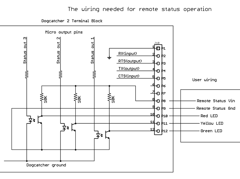
If the RemoteStatus option is set to TRUE in the configuration file, these lines will provide simplified status information as follows:
- If a USB stick is plugged in, the line corresponding to the green LED will be at high logic level.
- If there is a file open, the yellow LED line will be at logic high, otherwise it will be low.
- If there is an error, the red LED line will be at logic high.
In this mode of operation, a logic high will correspond with the VIN supplied to the terminal block, and the terminal block outputs will not flash with the device LEDs. The input impedance of your device must be high or it will load down the output and you will not measure as wide a voltage swing on the status / LED outputs.
Push button for closing file
When the push button is activated, the Dogcatcher 2 will close the file on the USB stick, and suppress writes for 6 seconds. Once the capture file has been closed, the user has 6 seconds to safely remove the USB stick. Removing the USB stick while the amber light is solid on will usually cause loss of data and, in rare cases, USB stick file system corruption. The switch input on the terminal block may be used in place of the push button.
Filenames used by Dogcatcher 2
In the filename, upper and lower case letters may be used interchangeably.
| ActualConfig.txt | Written to any USB stick inserted. This file is the actual, current setup. It should be compared to config.txt to ensure your intended settings are reflected. |
| Capture.txt | The default filename for data which is logged. |
| Config.txt | Is how the user specifies the settings for the Dogcatcher 2. |
| Configerr.txt | Tells which line of config.txt was not parsed properly. |
| Err.txt | Gives details of error indicated by red LED. |
| SaveUserDefaults.txt | See “To Use Configuration Options” |
| SetTime.txt | See “Timestamping” |
Dogcatcher Dimensions
The outer case dimensions are the same for all versions of the data logger. The DB9 connector is shown. The DB9 is replaced by a recessed terminal block on the embedded Dogcatcher 2.

FCC Compliance Statement
This equipment has been tested and found to comply with the limits for a Class B digital device, pursuant to part 15 of the FCC Rules. These limits are designed to provide reasonable protection against harmful interference in a residential installation. This equipment generates, uses and can radiate radio frequency energy and, if not installed and used in accordance with the instructions, may cause harmful interference to radio communications. However, there is no guarantee that interference will not occur in a particular installation. If this equipment does cause harmful interference to radio or television reception, which can be determined by turning the equipment off and on, the user is encouraged to try to correct the interference by one or more of the following measures
- Reorient or relocate the receiving antenna.
- Increase the separation between the equipment and receiver.
- Connect the equipment into an outlet on a circuit different from that to which the receiver is connected.
- Consult the dealer or an experienced radio/TV technician for help